
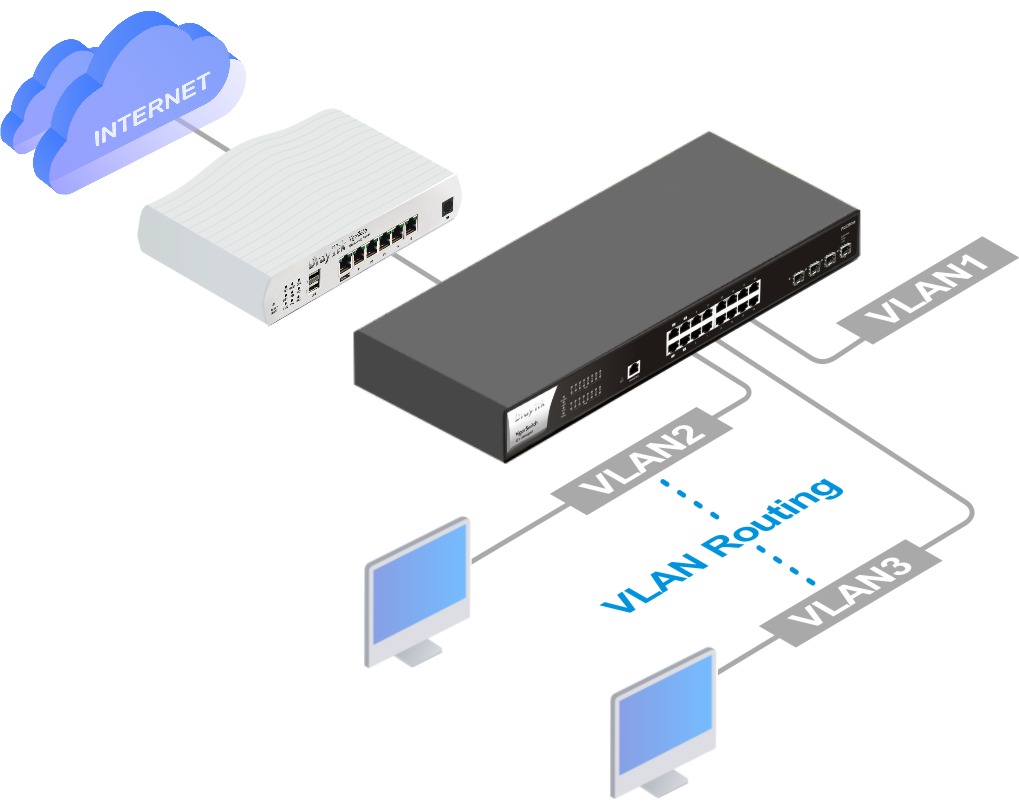
VLAN Routing on Vigor L2+ Switch
Vigor Router can separate different networks at Layer 2 (MAC level) with 802.1Q VLAN tags and have the ability to route the traffic between VLANs.
Supposing there is a device connected under a switch and the gateway is set to Vigor Router. The switch will add a VLAN tag for the traffic from this device and forward it to the Vigor Router, then the router will route this traffic to the other VLAN.
In this case, the routing performance between VLANs may be limited by the router's physical link. Take Vigor2866 and PQ2200xb for example, instead of the 2.5Gbps link speed, the routing throughput between VLANs is limited by the 1Gbps uplink to the Vigor2866.
Vigor L2+ Switch PQ2200xb and P2540x can be used to perform routing between separate networks at Layer 3 (IP level) for higher performance.
This article demonstrates how to configure VLAN routing on a Vigor Switch.
Vigor2866 LANs:
LAN1: 192.168.66.1/24, untagged
LAN2: 192.168.67.1/24, VID 20
PQ2200xb
VLAN1: 192.168.67.254/24, VID 20
VLAN2: 192.168.100.254/24, VID 100
VLAN3: 192.168.200.254/24, VID 200
Vigor Router Setup
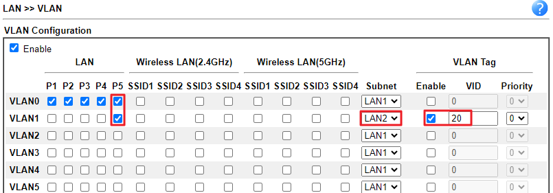
1. Go to LAN >> VLAN to enable the VLAN function and configure it as follows.
- VLAN0 LAN1: is the management network used to manage router's and switch's WUI interface.
- Include all the LAN ports
- Select LAN1 Subnet
- Leave the VLAN tag disabled
- VLAN1 LAN2: is the network where the switch's uplink is connected.
- Include the LAN port to which the switch is going to connect
- Select "LAN2" for Subnet
- Enable VLAN Tag, and enter a number for VID. Here we set VID as 20.
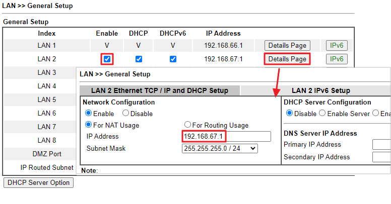
2. Go to LAN >> General Setup. Enable LAN interfaces and edit the IP as follows.
- LAN1:
- IP 192.168.66.1
- Subnet Mask 255.255.255.0/24
- LAN2:
- IP 192.168.67.1
- Subnet Mask 255.255.255.0/24
3. Go to Routing >> Static Route. Add two routes for LAN3 and LAN4 which point to the switch's LAN2 interface IP which will be configured later in the switch setup.
- Route1:
- Destination Address 192.168.100.0/24
- Gateway IP Address 192.168.67.254
- Network Interface LAN2
- Route2:
- Destination Address 192.168.200.0/24
- Gateway IP Address 192.168.67.254
- Network Interface LAN2
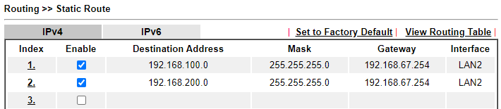
Since LAN3 and LAN4 are created on the switch, it is needed to add these two routes on the router to forward the incoming traffic back to the devices.
Switch Setup (For the model PQ2200xb)
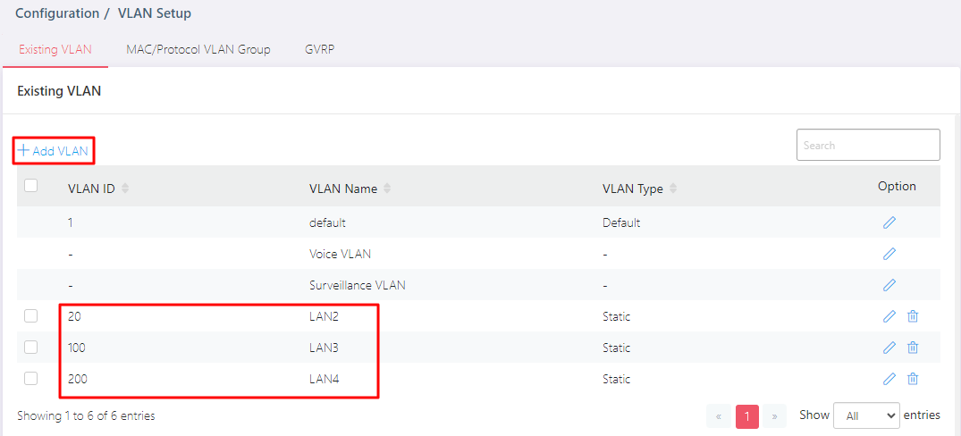
1. Go to Configuration / VLAN Setup. Add VLANs for LAN2, LAN3, and LAN4.
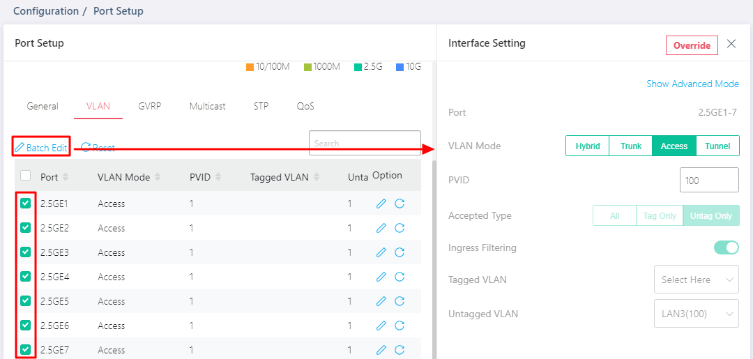
2. Go to Configuration / Port Setup. Set up the ports devices and the router would be connected in the VLAN tab.
In this article,
- GE1~GE7: LAN3 devices
- GE8~GE14: LAN4 devices
- GE16: Uplink connected to the router.
We can select multiple ports and click Batch Edit to configure them at once.
GE1~GE7:
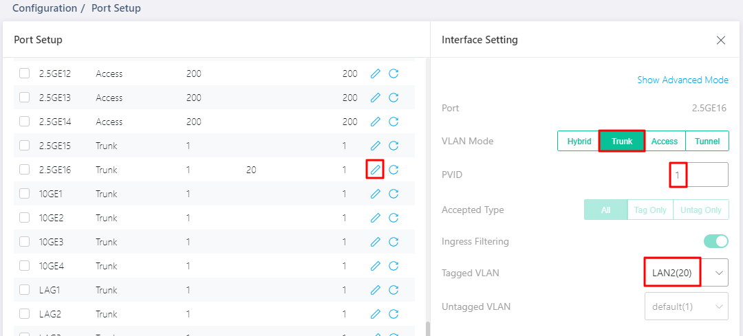
GE16:
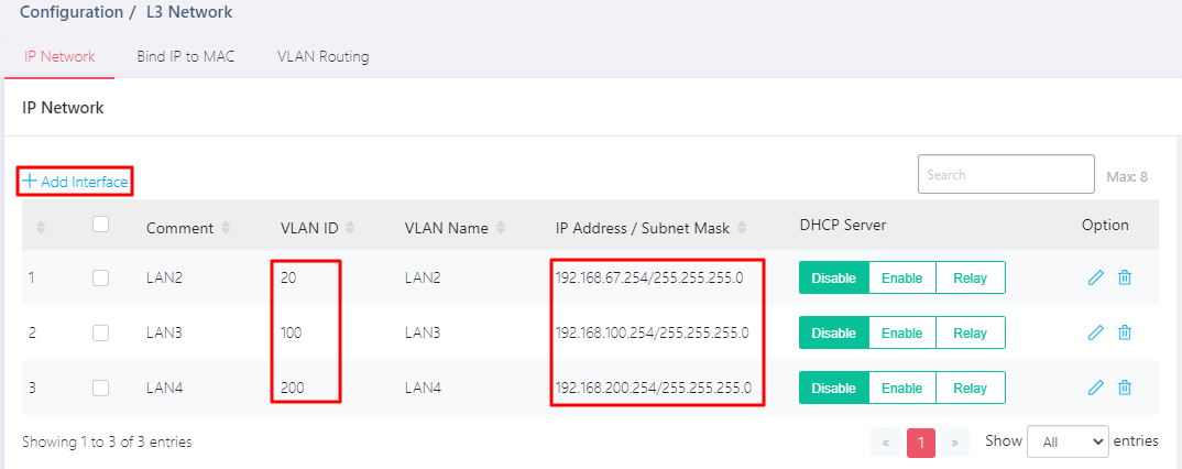
3. Go to Configuration / L3 Network. Add the interfaces of LAN2, LAN3, and LAN4 for VLAN Routing in the IP Network tab.
- LAN2:
- VLAN ID 20
- IP 192.168.67.254
- LAN3:
- VLAN ID 100
- IP 192.168.100.254
- LAN4:
- VLAN ID 200
- IP 192.168.200.254
Note:
Management VLAN interface cannot be used for VLAN routing.
4. Enable DHCP Server for LAN3 and LAN4.
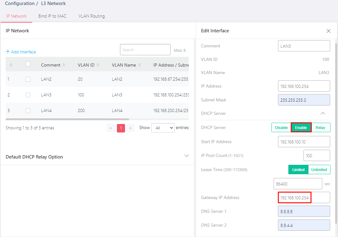
The LAN DHCP Gateway configuration must be set to use the Switch's VLAN Routing interface address, configured in step 3. Take LAN3 for example, 192.168.100.254 is the switch's VLAN Routing interface address. Once the traffic is sent, it will be forwarded to the switch's VLAN Routing interface. Then the switch routes the traffic to the other VLAN.
5. In the VLAN Routing tab, switch on the option VLAN Routing Enabled and configure it as follows to assign a default route for devices connected to the switch.
- Select Gateway as Next Hop.
- Enter router’s LAN2 IP as Gateway IP Address. Here we set it as 192.168.67.1.
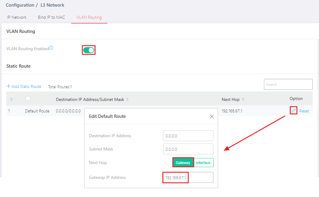
It is important that the Gateway of the Default Route points to one of the Router's interfaces. Otherwise, devices connected to the switch will not be able to access the Internet.
Switch Setup (For the model P2540x)
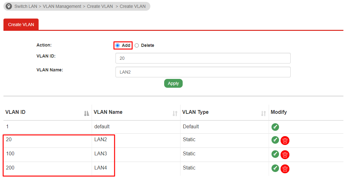
1. Go to Switch LAN > VLAN Management > Create VLAN. Add VLANs for LAN2, LAN3, and LAN4.
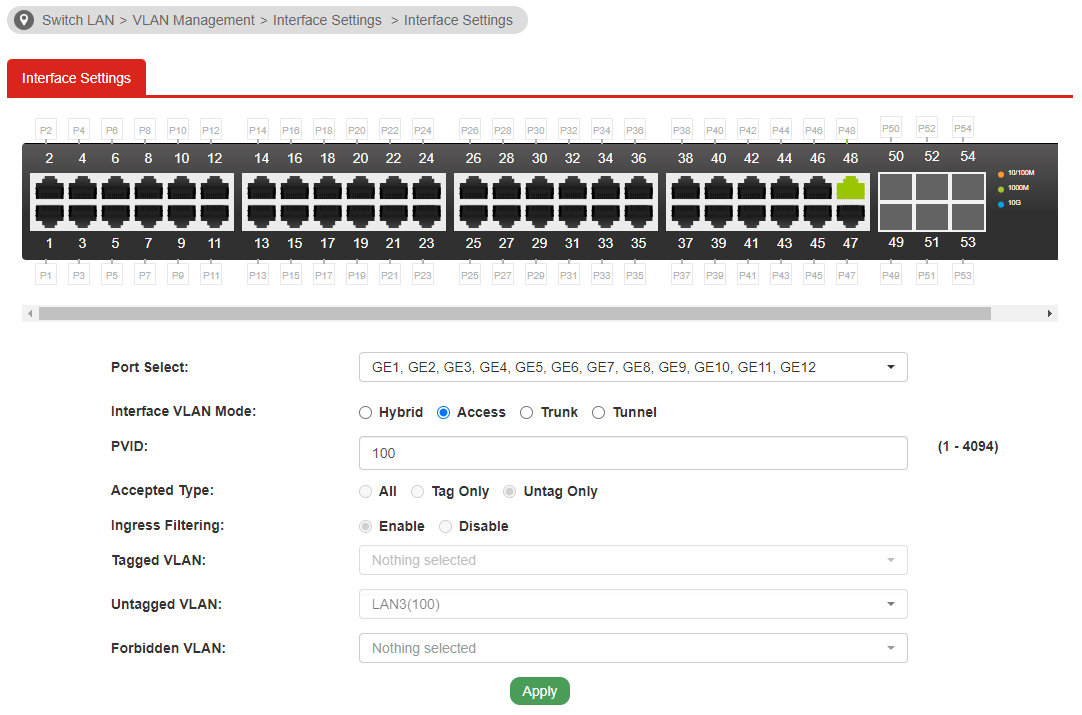
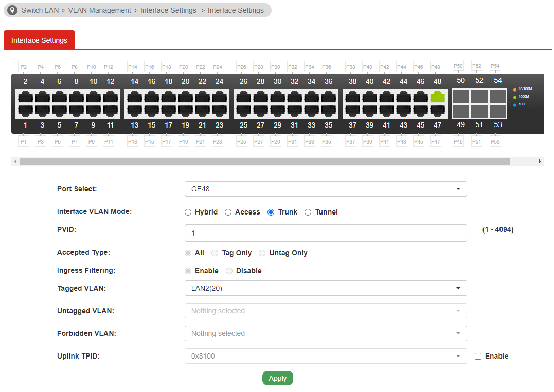
2. In the Interface Settings. Set up the ports devices and the router would be connected.
In this article,
- GE1~GE12: LAN3 devices,
- GE13~GE24: LAN4 devices,
- GE48: Uplink connected to the router.
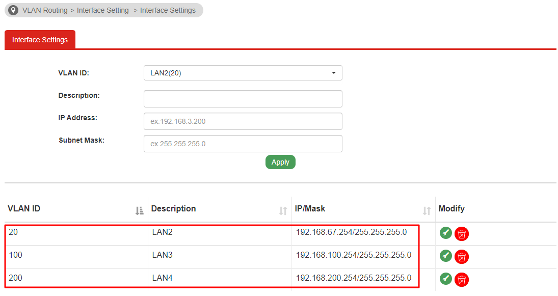
- LAN2:
- VLAN ID 20
- IP 192.168.67.254
- LAN3:
- VLAN ID 100
- IP 192.168.100.254
- LAN4:
- VLAN ID 200
- IP 192.168.200.254
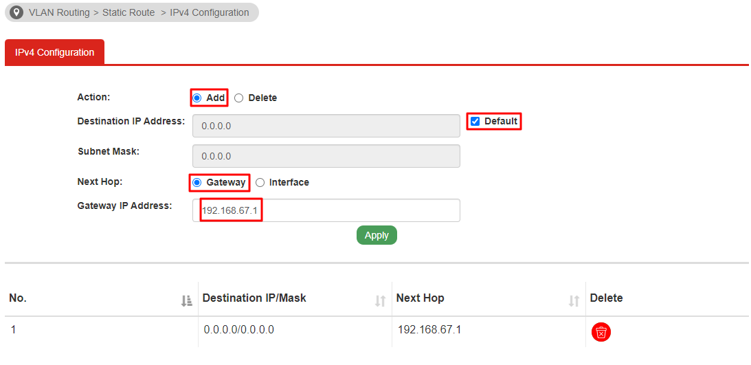
- Select Add.
- Tick Default.
- Select Gateway as Next Hop.
- Enter router's LAN2 IP as Gateway IP Address. Here we set it as 192.168.67.1.
GE1~GE12:
GE48:
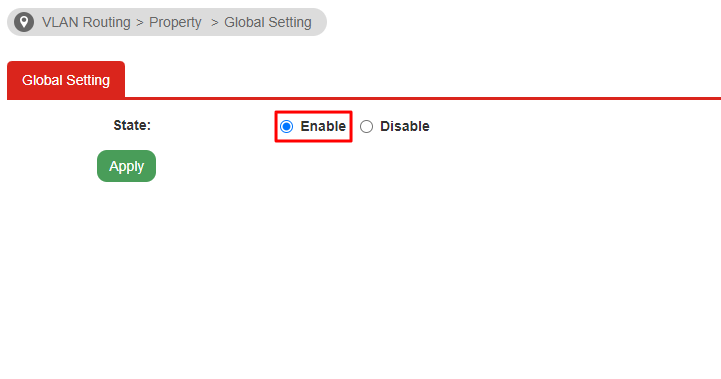
3. Go to VLAN Routing > Property > Global Setting. Enable the VLAN Routing.
4. In the Interface Settings. Add the interfaces of LAN2, LAN3, and LAN4 for VLAN Routing.
5. In the IPv4 Configuration, configure it as follows to assign a default route for devices connected to the switch.
6. Go to Switch LAN > DHCP Server > DHCP Server Settings. Enable DHCP Server for LAN3 and LAN4.
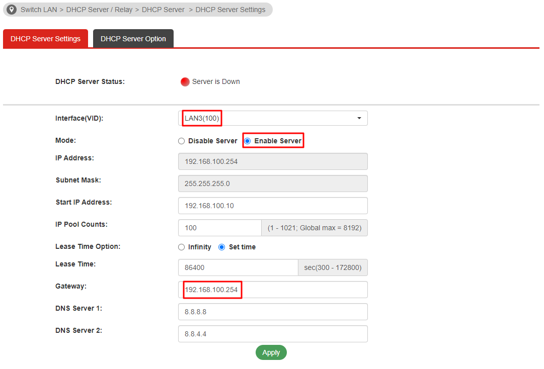
The LAN DHCP Gateway configuration must be set to use the Switch's VLAN Routing interface address, configured in step 3. Take LAN3 for example, 192.168.100.254 is the switch's VLAN Routing interface address. Once the traffic is sent, it will be forwarded to the switch's VLAN Routing interface. Then the switch routes the traffic to the other VLAN.
Verify the Configuration
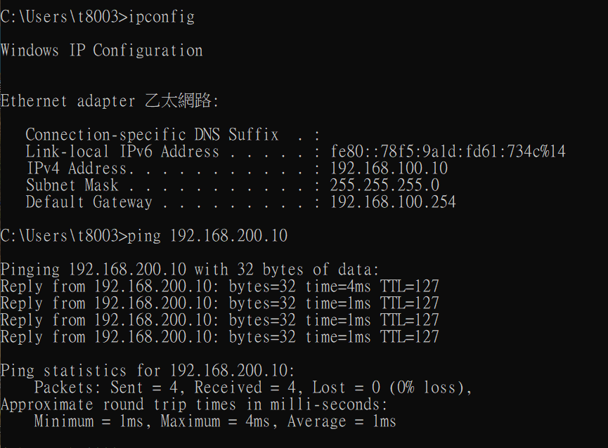
Try to connect two PCs to GE4 and GE10.
PC1 gets the IP 192.168.100.10, the default gateway is 192.168.100.254 and can ping 192.168.200.10.
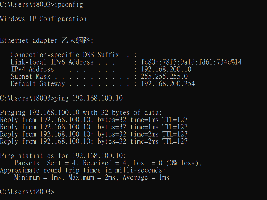
PC2 gets the IP 192.168.200.10, the default gateway is 192.168.200.254 and can ping 192.168.100.10.
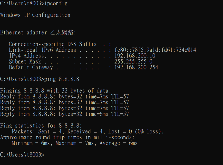
Both PC1 and PC2 can access the Internet.
Published On:2024-08-19
Was this helpful?